
Tall Frappe WiPi Latte Part I – Hacking In
You could make this hardware as over complicated as you want – reverse engineer the whole machine and some. but in order to keep this all as simple and reliable as possible and given we have more than enough I/O we’re simply going to recreate the control board as a new PCB with headers to attach to the raspberry pi. This will require 8 I/O connections
- 4x inputs – these are for the shift register and I2C
- 4x outputs – these are for the button outputs and I2C
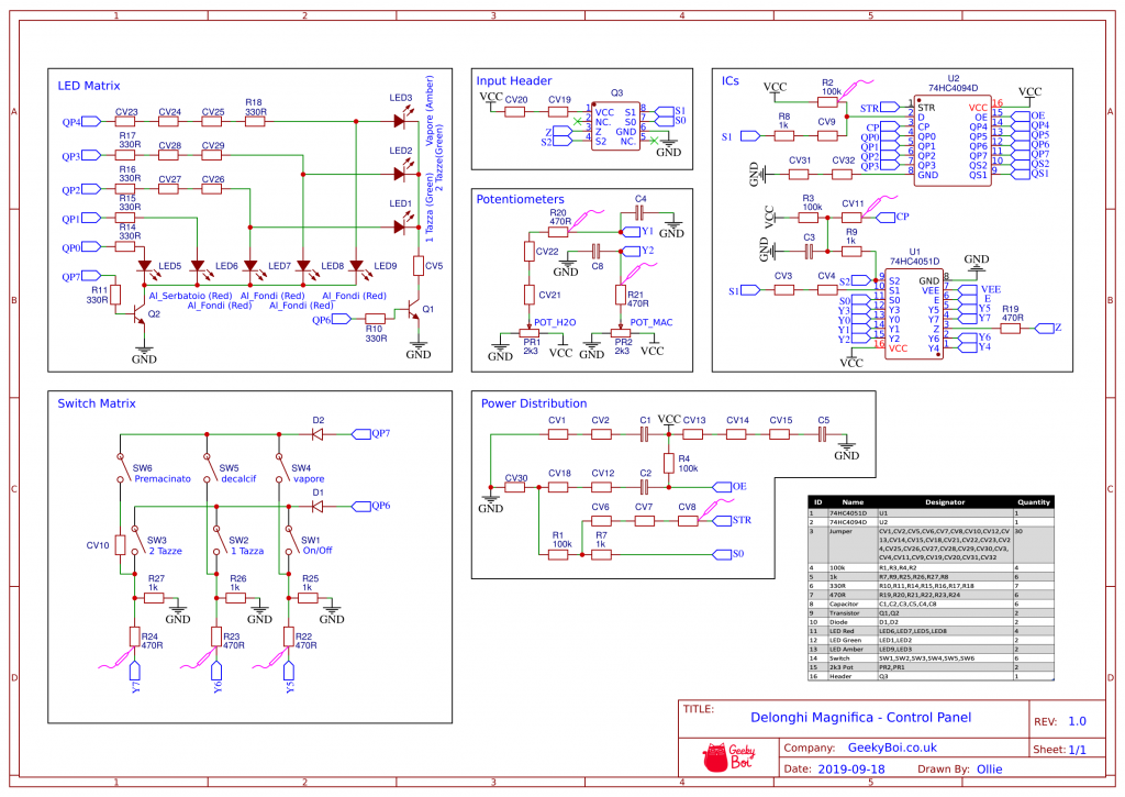
The BOM for the current board is and a schematic is shown below.
- 30x 0ohm resistors (jumpers)
- 23x resistors (4x 100K, 6x 1K, 6x 330R, 7x 470R)
- 6x capacitors – still need to work out values
- 2x transistors
- 2x diodes
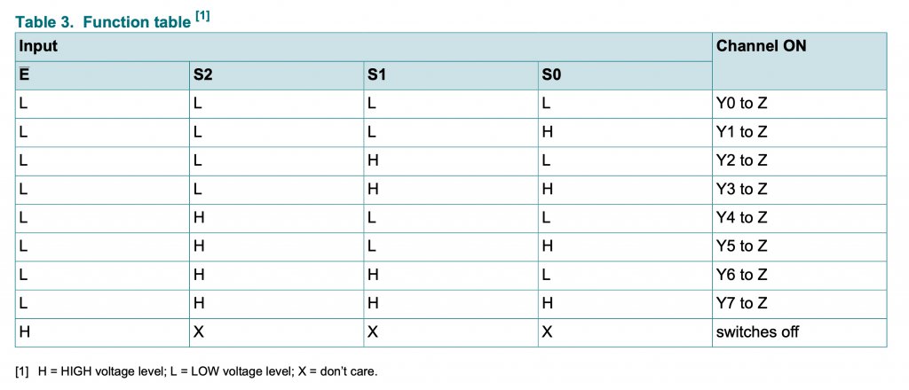
- 1x 74HC4051
- 1x 74HC4094 – shift register
- 8x LED
- 6x Switch
- 2x Potentiometer (2K3)
Prototyping
So now we know how the board works it’s time to figure out the best way to simulate it using a micro controller or micro processor.
One option is a raspberry pi zero W has a LOTS of GPIO but we can’t guarantee the timing as it’s a microprocessor. So our best bet with this would be to add some logic gates before hand to handle all the fast time critical stuff and use that massive array of GPIO to read all of the signals directly in and out. This would need 14 pins to handle the LED status in and buttons out. The pi also gives a really easy development environment for adding Alexa capability, mobile phone interface and a simple HDMI touch screen.
The other potential option is an ESP32. This could also work great as it’s more than powerful enough. Could directly read the S0, S1, S2 signals and has built in wifi. The downsize is that the coding will be much more complicated in order to get it fast enough to catch every signal. It is dual processor but that’s a real scary rabbit hole we’re jumping down with that. It’s also going to be much harder to add any kind of mobile phone interface that looks good and we’d need to look at reprogrammable serial based touch screens.
On reflection by far the easiest and most customisable solution is the pi based choice. It’ll give us a huge amount of flexibility when designing the user interface and we can handle the timing critical coffee machine interface stuff with simple digital logic ICs.
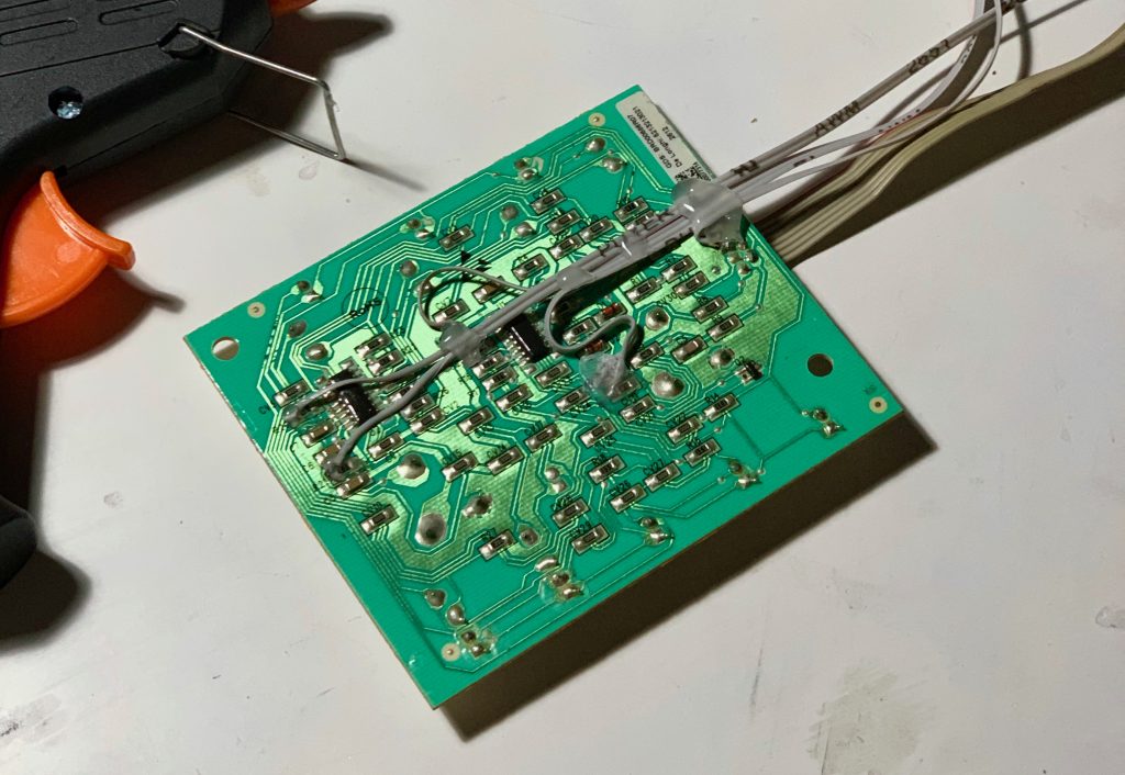
Now we can modify our donor board to connect it to our raspberry pi. We’ll need to add 10 connection points to: +5V, GND, Y1, Y2, Y5, Y6, Y7, S0, S1 and S2. These are connected to the probe points indicated in schematic above in pink. We’ll also need to disconnect the wiper connection for the two potentiometers so we can inject our own signal.
I’ll started off by adding some breakout wires to a control board PCB I got off eBay. This will give a really simple way of debugging the logic circuit we need to build
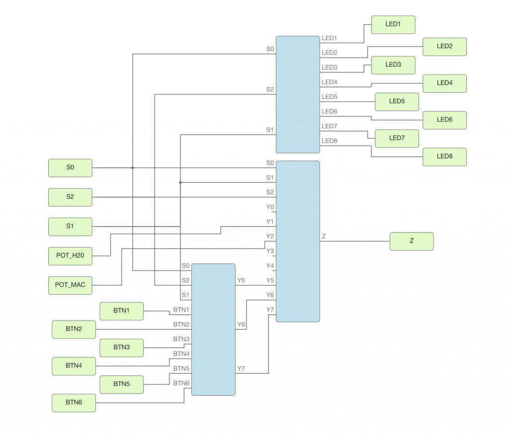
Next we’ll start figuring out what logic ICs we need. To do this I’m going to be using a piece of software called icestudio and a tiny FPGA bx board. This will allow me to very quickly refine and debug my digital logic circuit.
Final Design Specification
- 1x demuxer
- 1x shift register
- 6x logic level shifter
- 12x d type flip flops
- 9x AND gates
- 3x OR gates
- 1x Raspberry Pi Zero W + header
- 1x 6″ capacitive touch screen + cables
From our testing and research in theory we should be able to control the whole coffee machine by reading in S0, S1 and S2 and outputting to Z through a potentiometer. Whether in practise we can implement a system fast enough to do this is another question. I think we may end up implementing the multiplexer which would significantly simplify the software eliminating the timing critical button presses. We could probably get away with 3 buttons as we know the shift register flips the selection. so would only need to flip the signals after every other strobe pulse.
We’ll pull the LED statuses from the shift register signals and output to Z via a potentiometer as this will allow us to send both the digital and analogue signals required.
Unfortunately due to the speed of the signals we’ll have to interface to the raspberry pi through another micro processor or some I/O interface. I’m thinking something like an ESP32 should do the trick. It’s a wifi connected board that we could shove some kind of JSON based control system on to to act as a go between our client and the coffee machine. This takes the heavy high speed lifting of monitoring and controlling the coffee machine off of the raspberry pi and overall simplifies the project.
We could also look at an I2C based expansion board. They’re lots available already for the raspberry pi so getting hold of one shouldn’t be too difficult.
In the next article we’ll look at how to turn our new found knowledge in to a fully featured “smart” coffee machine
Additional Resources
Below are some links to articles I found whilst making this project. Steve’s Alexa powered coffee machine article goes in to a lot more detail on how the two boards in the coffee machine communicate with each other and implements his solution almost entirely in software. My design took elements of this but we used the easier method of not trying to replicate the communication with the rest of the coffee machine only the shift register.
The zhipwhip Textpsresso machine is based on the previous generation esam3300 but it’s still a useful article to refer to.
Ollie
An electromechanical systems engineer with passion for all things technology, design and feline.

New Defender
You May Also Like

Arduino + MusicCast
9th September 2019